 |
 |
|
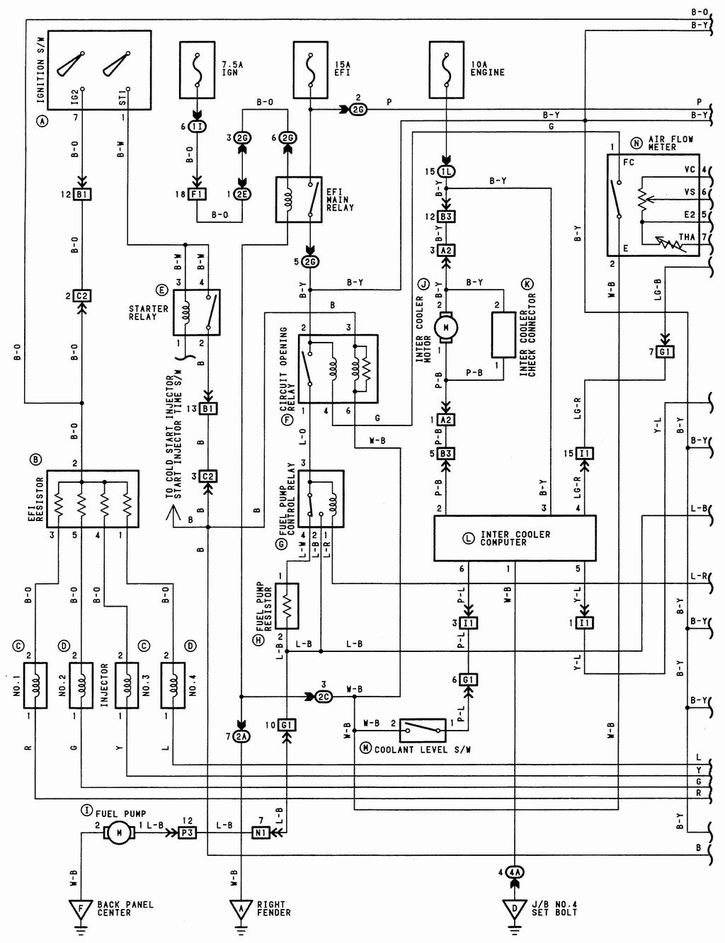
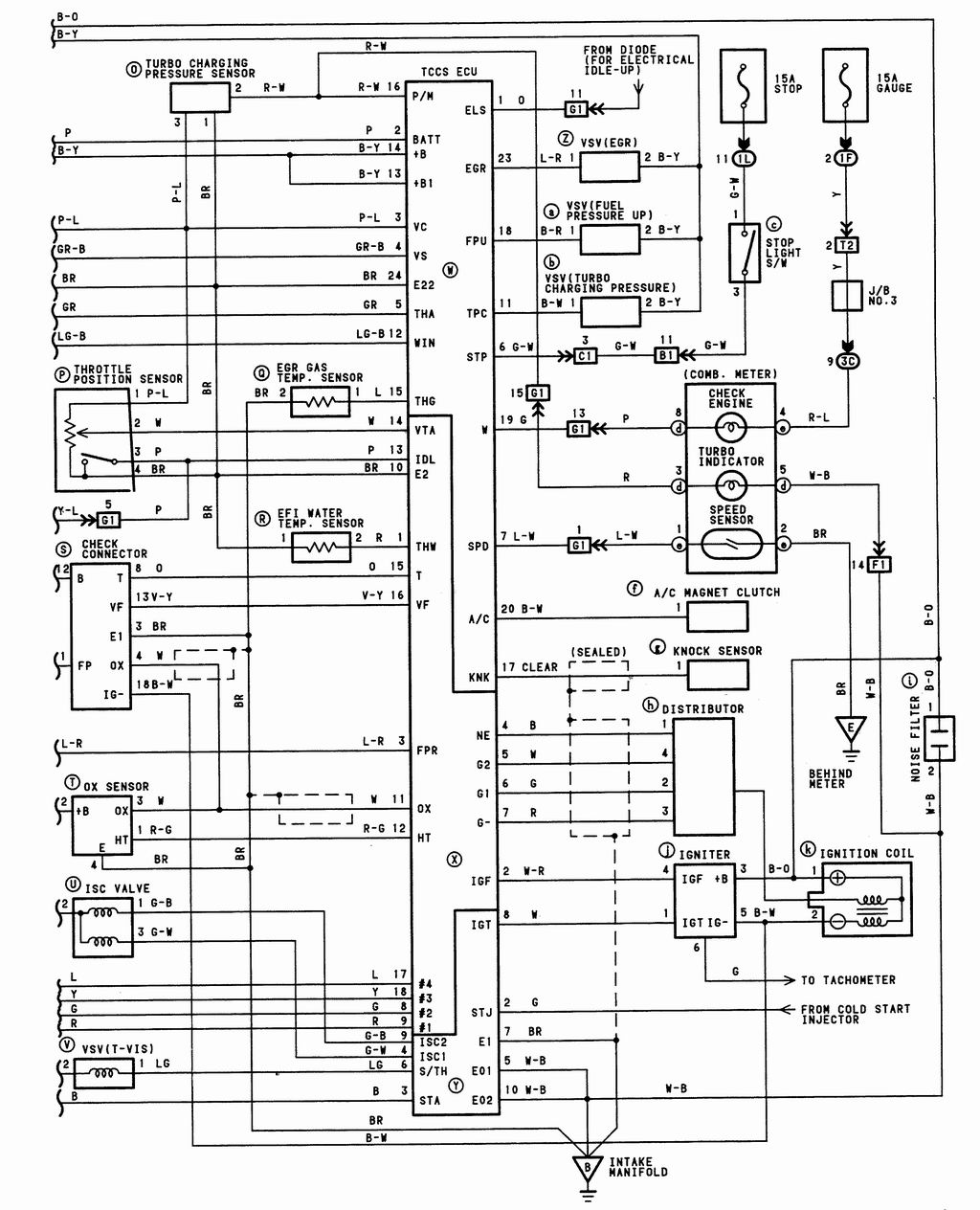
| The original 165 ECU wiring diagram | The other half | My wiring diagram |
Under construction...
HALTECH INSTALLATION
Er, is this a home DIY job?
Yes. It looks fairly complicated when you first start but it's not too bad. It helps a lot if you understand what you need to install for an ECU to run an engine, and what the sensors and gizmos actually do!
Any tips before I go mad and start installing one of these?
Understand carefully how the E6K, or pretty much any ECU, is going to control the engine. This will make the install and setup a lot easier. Order all the bits you need and have them in your hands before you start or a tricky job may turn into a long protracted nightmare.
I cannot recommend highly enough you source you electrical components from these guys - www.vehicle-wiring-products.co.uk . I'm sure that they will have all the bits and pieces that you will need to complete the wiring and loom etc...
The wiring diagram supplied by Haltech I found to be confusing and poor, and I'm conversant with wiring diagrams, I do this amongst other things for a living...
What "stuff do you need to buy in order to install and run one of these?
Did you do a wiring diagram?
Yes. I highly advise sitting down for a few hours and going through the original Toyota loom wiring and then comparing this to how you will wire your ECU and ancillaries. I think you would find trying to wire the ECU up without a guide very very difficult.
|
|
|
| The original 165 ECU wiring diagram | The other half | My wiring diagram |
What's all those numbers in your wiring diagram?
I installed a junction box, (JB), in the car, and then connected the loom and the ECU to the JB.
How long did it take you?
From removing original loom through to manufacturing new loom and starting the car approx 2 full days. Before this I spend a considerable amount of time finding out details of sensors, sourcing wiring, "bits and pieces" and wiring diagrams.
What do all the sensors do?
In brief:
| Sensor | Purpose | Anything else? |
| Throttle position | Informs ECU of throttle position | |
| Air temperature | Measures air temp entering cylinders |
|
| Igniter | Charges/fires coil |
|
| MAP | ECU uses this to determine the load on the engine |
|
| Coolant | Water temperature |
|
| Fuel pump relay | Switches on/off the fuel pump |
|
| Dizzy trigger i/p | Informs the ECU of whereabouts the engine is in it's "cycle" |
|
| Oxygen sensor | Allows ECU to correct fuel maps based on this input |
|
| Boost solenoid | Allows ECU to control boost pressure |
|
| Radiator fan | Cools radiator/coolant |
|
| Injectors | Stick fuel into the cylinders |
|
| Road speed | Car speed | |
Any other points to note?
Got a handy guide how to install this thing?
Sort of...I didn't take many pictures. My method was little more unconventional than normal installations. I placed a JB immediately by the ECU instead of running all the wires from the ECU out into the engine bay etc. The reason I did this was so that I can quickly monitor signals and also I have a greater flexibility with the connections i.e. if I had fouled up then rather than re-run a wire I could just change it over at the JB, also if I wanted to change the configuration I was running then I just have to remove the cover and move some wires around, rather than split the wiring loom...bit of a pain! This also creates a very handy point for monitoring signals and picking up power supplies for other instruments.
I have written this as a helpful guide, not a step by step guide...
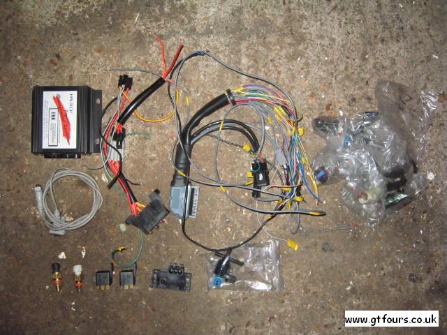 |
The complete kit looks something like this, only the supplied wiring loom is longer. This is everything you need - ECU, loom, air temp sensor, water temp sensor, MAP sensor, laptop lead and replacement connectors. Bottom middle you can see the optional boost control solenoid |
 |
Just the hardware - ECU, relays, Water temp sensor, boost solenoid and MAP sensor. The 2 relays are required for the fuel pump and for the radiator fan(s) |
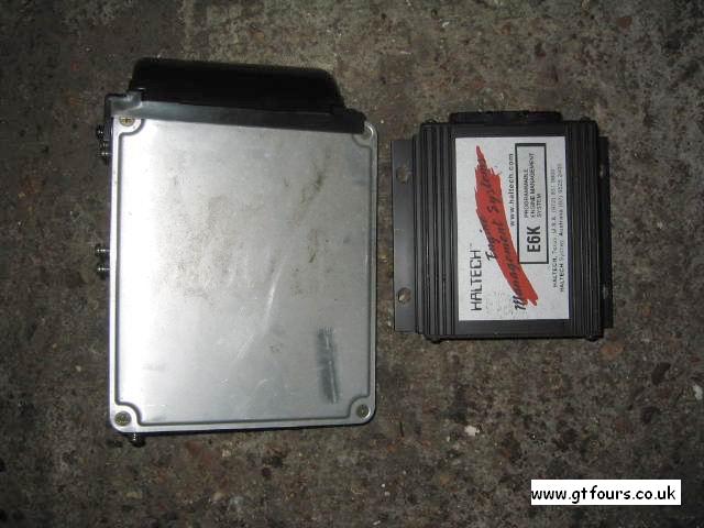 |
The old and new ECUs |
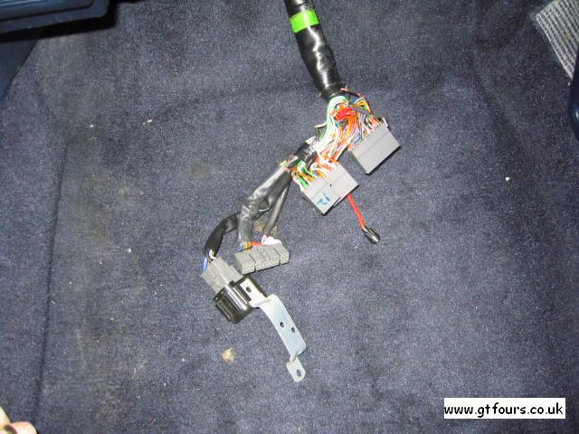 |
I removed the stock ECU and the circuit opening relay attached to the side of the ECU. Some of the wiring has to remain in place to drive gauges etc |
 |
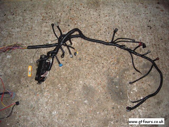
First up is to remove the complete loom
from the car. Unclip the 3 connectors from the ECU, remove the rubber
boot and pull this lot through into the engine bay. Unclip all the
connectors from all the sensors:
Then unplug the loom from the bottom of the main fuse and relay box - the majority of the loom can now be removed easily |
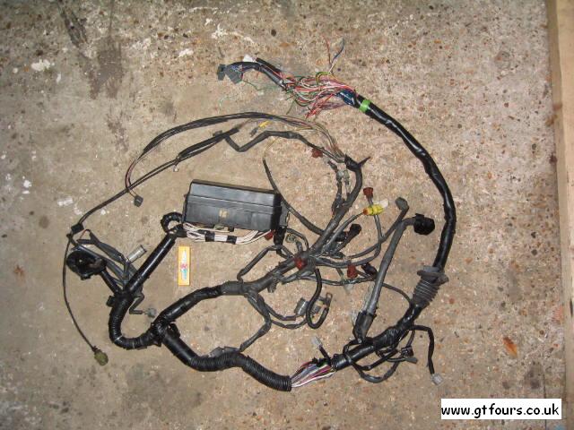 |
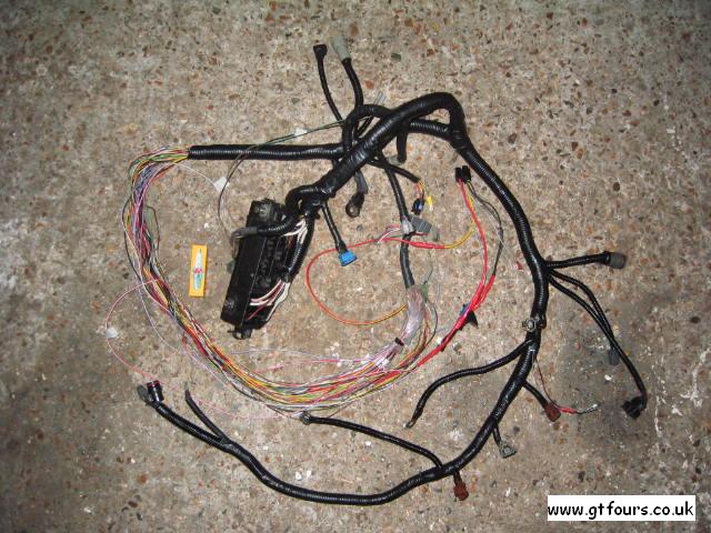
The removed loom |
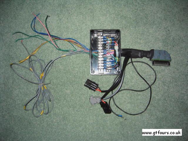 |
I took what seems to be a different approach to most people, and installed a junction box, (JB), immediately next to the connector for the ECU. This allows me to monitor all the signals to/from the ECU and to simply plug in anything I want to install e.g. gauge power supply, and ignition powered devices e.g. WI |
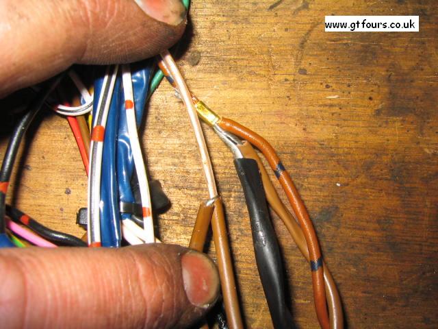 |
If you now open up the loom you will see that many of the wires are crimped together... Many of these wires are either going to be redundant or you will be running new wires |
 |
I mounted the air temp sensor in the hole that the CSI left under the throttle body. By carefully manufacturing a plate it can be bolted up securely beneath the throttle body |
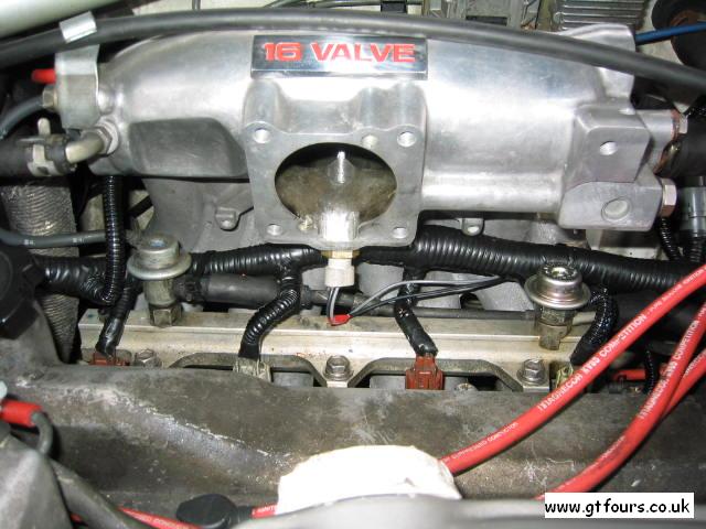 |
Trial fitting the sensor... |
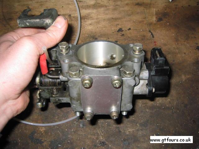 |
I removed the stock ISC and fitted a blanking plate over the bottom of the throttle body. Whilst this is fine, on reflection this is a mistake not to run the car without any form of idle stabilisation... |
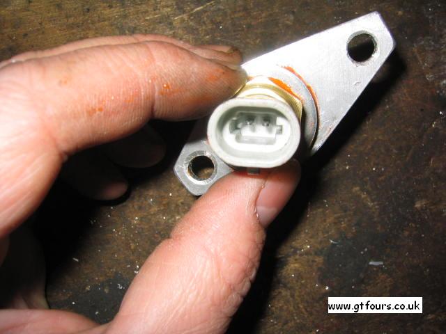
| The water temp sensor is mounted in the original hole that the old ECU water temp sensor leaves behind. I believe this is an M12x1.5 thread, however the sensor I was supplied with used a 1/4"? NPT thread. I simply drilled out the water elbow and tapped this to take the new sensor. I have heard that this sensor is not absolutely necessary to be replaced, but if the stock unit is left this will read a few degrees out...The water temp sensor is available in the stock water elbow thread size - just ask for it! | |
 |
The loom part finished... |
 |
95% finished loom |
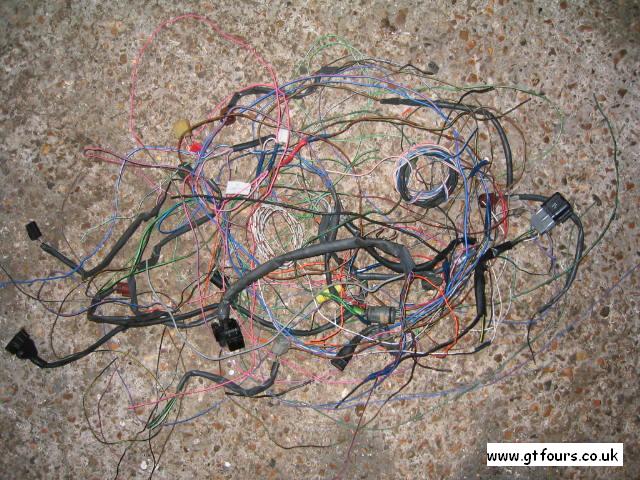 |
The amount of wiring removed from the old loom is quite surprising! |
| Next it is simply a matter of connecting up the sensors etc to the newly manufactured loom, connecting the laptop, loading in the starting map below and starting the car...good luck! |
Any other info?
A bit...
Lambda sensorBoost solenoid
Not essential but seems to be pretty worthwhile, and a lot cheaper than some
electronic boost controllers. This is simply a solenoid stuck in between the
wastegate actuator and the turbo hosing, similar to an
RV and the majority of
controllers. You can set a maximum boost pressure to not exceed. Boost is mappable vs rpm
in 500rpm increments. There are 2 maps to switch between that can
be stored in the ECU. I suppose with a little ingenuity a switch can be used to
manually switch between these 2 boost pressures - but I haven't looked into that
yet. At present the laptop is needed to switch between the two maps.
Radiator fan
The ECU can set at what temperature this comes on and goes off. It seems that
somewhere around the thermostat temperature makes for good operation. The ECU
activates a relay in order to cut the fan in.
Injector resistors
The stock ECU drives the injectors via a resistor pack. This is used to limit
the current drawn by the injectors, since they are low impedance injectors
~3ohm. I utilised this resistor pack in my loom. When I re-wire the loom I will
probably remove this and sink the injector current directly to the ECU. The ECU
has the ability to sink fairly large currents and will reliably cope with the
current.
Here are a couple of maps, with the basic settings enabling you to start the car...
| Maps coming... | 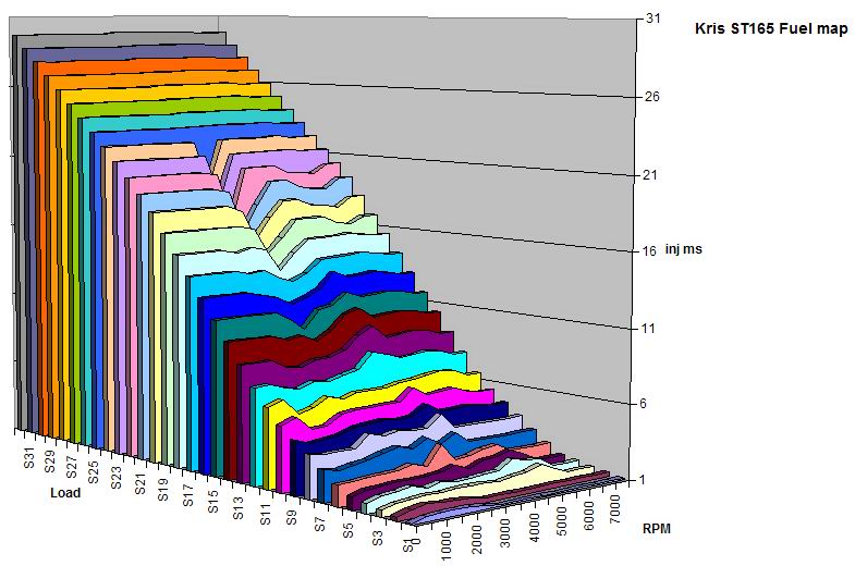 |
 |
|
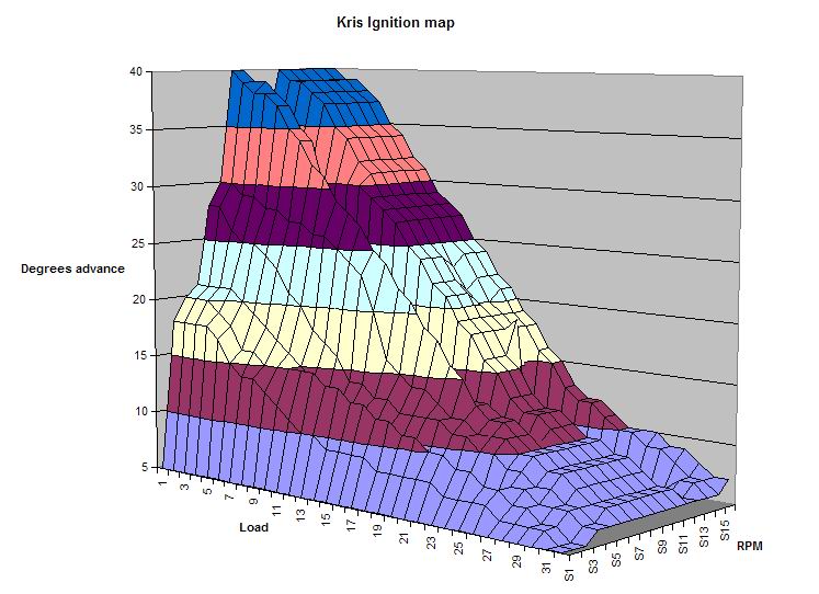
| Starting maps | Tweeked maps. Note the fuel and coolant will probably be inaccurate for your application, but other settings may be useful | Current fuel map, by no means finished | Current ignition map, same as fuel map - needs a lot more work |
I ran the starting map for approx 2 weeks at <5psi boost until I could verify that the maps were safe at the tuners. The map was pretty much rich all over, except in a couple of fairly low load areas on 3k-4k maps where it was very lean i.e. 19:1. The timing was fine, except in the 3k area where this was too far advanced and produced mild detonation. The car was mapped for 14psi on a 48mm hybrid CT26 turbo.
The manual is a bit vague, have you got any more info on these settings?
Yes. Hopefully what I'm writing is accurate, and can be found here
How are you getting on with this ECU?
Hmmmm. Most people will have a slightly tainted view, and swear blind that their ECU is the best etc etc. I am trying to remain very objective in my findings and cut the waffle - this ECU seems pretty good, costs less than others, but I do not have a direct comparison. One of the most appealing things is that the ECU can be setup by an enthusiast at home, whereas other manufacturers will not release their software and/or you require specialist leads and equipment to program the damn thing! Whilst this prevents "tweeking" it can also prove very costly as a trip to the tuners may be necessary to sort that niggling cold start problem, or a small adjustment to the maps etc.
I have learnt a lot from installing this and tuning it, and the more I learn the more important I find it is to get the thing setup properly. I found that not a lot of info is around for correctly setting up the different values, and I have learnt by trial and error what's the correct way...I hope I am now on the correct path! I will post my findings here as I learn more. Time will tell if I get it right...